 PDF Download
ADJUSTMENTS

• Stop the engine and pull out the ignition key and remove the power take-off drive always before proceeding to adjustments, maintenance, lubrication, cleaning etc!
GENERAL POSITION ADJUSTMENTS
CONNECTION SETTINGS

• Make sure that machine is positioned with tractor on a smooth and plain surface in order to carry out connection settings.
 • Adjust the height by setting tractor’s hydraulic control level to position control.
When you move the hydraulic lever slightly in position control mode, machine rises up and stops at a certain level, when you move the lever again, it rises up a little bit higher and stops again; so it doesn’t reach the highest point as in tow control mode.
Note: It is kept at a certain level by taking up the hydraulic lifting-landing arm. In this case tool and machine rises up completely, preselection lever is in “TOW CONTROL” mode. If tool and machine don’t rise up fully but to a certain level, it is in “POSITION CONTROL” mode. Position control mode ensures that machine operates on ground by keeping the machine at certain level.
While the machines like vertical mulcher are operated, preselection lever should be in position control mode.
• It should be parallel to soil surface while machine is running. Right-left and front-back lines should be aligned very well in parallel for a balanced operation before running the machine.
• Align left and right lines of your machine in parallel by the use of right and left hanging rods suited on the hydraulic three-point hitch system in order to ensure parallel alignment of main body of your machine.• Upper linking rod of tractor allows front-back parallel alignments for the machine attached by being shortened and extended. A gap should be available between round journals in the holes at the side where upper linking rod is connected to both machine and tractor and shafts attached to the said journals!
CYLINDER ADJUSTMENT
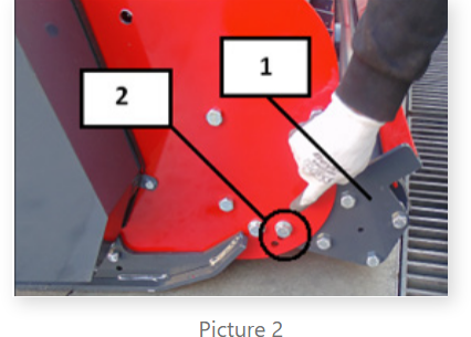
Cylinder should be adjusted before working with machine; in this way cutting/mulching height should be adjusted in most appropriate way for the working area and product.
• 3-stage holes on the side panel sheet (2) are used for this purpose. When the adjustment hole on the cylinder connection plate (1) is set side by side with the appropriate one from the holes on side panel sheet, adjustment will have been completed by fixing them with bolts at both sides in same way (See Picture 2).