PDF Download
PTO Shaft
GENERAL

• Place PTO shaft on the ground, stop the engine and pull out the ignition key and disengage PTO shaft before proceeding to calibration, maintenance, cleaning, greasing etc. as well as attachment to and detachment from tractor! Make sure that there is no one between tractor and machine unless no measure was taken by supporting it with braking mechanisms or wedges in order to eliminate sliding risk!
• Never operate the PTO shaft in case of transport while attached! Material damage and risk to drop and to be lost are in question!
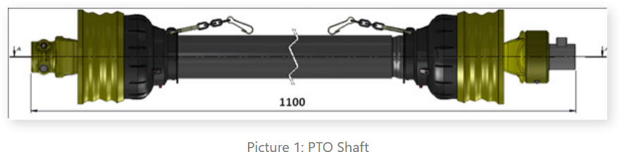
PTO shaft which transmits the movement from tail spindle of tractor to machine’s transmission is equipped with the joint which should be fixed to machine side and has an overrunning clutch (provided with machine and shaft recommended in case of need: EGE ŞAFT, Series 6, Overrunning clutch, 1100mm closed joint total length) See Picture 1.
Overrunning clutches protects the shaft against the inverse power occurring due to high inertia of rotating parts.
 • These safety arrangements are made up of ratchet ball suited on the shaft fork, ratchet pipe and ratchet spring inserted in the holes on ratchet ball and ratchet lock.
When a running tractor is stopped or rotating speed is reduced, agricultural machine continues to work at high rpm. This sudden stop or slowdown will harm the machine or tractor. Nevertheless ratchet part of the shaft attached to the machine rotates independently from the shaft due to the movement of machine. In this way risk is eliminated. Overrunning clutch of the shaft is attached to machine side.
FITTING AND ASSEMBLY
• If the length of the shaft that you use while attaching your tractor to machine is long, shaft bends while lifting and operating the machine. Adjust appropriate shaft length as recommended!
• Shafts used in agricultural machines are manufactured with joint and adjustable length.
• You should complete the attachment of machine to tractor as recommended first with three-point hitch system in order to adjust the length of shaft.
If attachment of machine to tractor is ok, take following steps respectively!
• First measure the distance between the extreme point of tractor’s tails spindle and extreme point of machine’s transmission output shaft. Note the related value.• Second measure the distance between the pins which are available at the both sides of shaft and ensures that it is fixed when placed to both tractor and machine sides as seen in Picture 2. Note this L value.
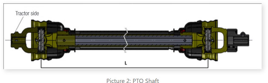
• The distance between the extreme point of tractor’s tail spindle and extreme point of machine’s transmission output shaft and value (L) recorded should be equal. If L value is higher, shaft should be cut to appropriate size in order to achieve the said equality.
• Pull and remove it by holding the shaft with both sides of junction before cutting it. So shaft is divided in two parts.
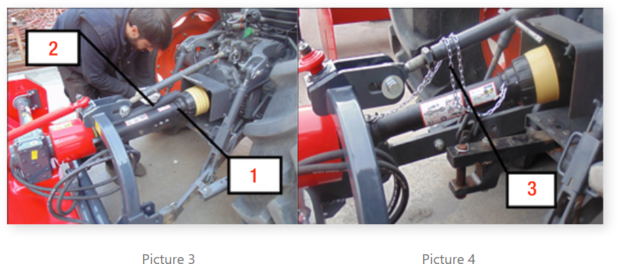
• Insert the side bearing tractor picture and the side with overrunning clutch to tails spindle (2) and Machine (1) respectively and take both halves side by side and mark them with both sides (See Picture 3).
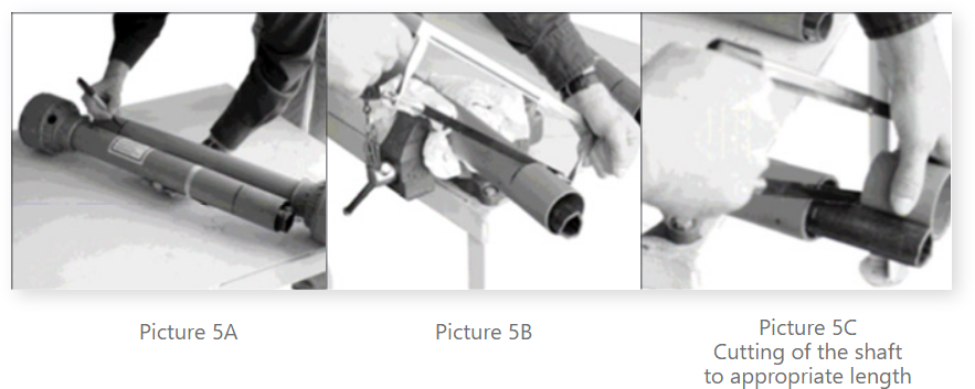
• It is necessary to cut the shaft at both sides as much as the difference between both values! (See Picture 5 A/B/C).
For instance; let’s say that the distance between the extreme point of tractor’s tail spindle and extreme point of machine’s transmission output shaft is 100 cm and that Length L, the distance between left and right pins of the shaft is 110cm. In this case you cut the shaft 10 cm at the both sides that you divide in two parts. (It should be noted that the said shortening shall be reduced to 10cm since one of these two parts are placed within the other one even though it seems that it should be cut 20 cm totally!
• Finally complete the attachment of machine to tractor by connecting PTO shaft; clean and grease the transmission output shaft of machine and tail axle for this purpose. After that, scroll it on PTO shaft until pin fits completely. Sliding gap for shaft should be minimum 5 cm and maximum 15 cm.
• Affix the shaft and tractor’s tail spindle at the same time and protective pipe and protective funnel of transmission output shaft at the machine and position it in accordance with the rules! Make sure that protective pipe covering is affixed to contain the joints and secured by a chain for stability! (3) (See Picture 4).
• When the angle of deviation which is the angle between the axis of tractor’s tail spindle to which shaft is connected and tail spindle of machine’s transmission through which power is transmitted increases, running of shaft is of danger. In this case operation should be ended! (angle of deviation mustn’t exceed 30º !)
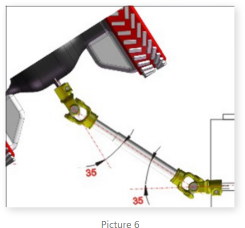
• Tractor should be stopped and operation should be ended, when the angle of shaft junctions exceed 35º. Only the junctions in wide-angle shafts may operate at up to 70º-80º based on their types (See Picture 6).